This guide was written assuming that you have no idea how to solder. If you already know how to solder, and just need the pinout, just jump to the bottom for a diagram.
If using a soldering/desoldering iron freaks you out, then I suppose it always will, and maybe you'll pass on trying this regardless -
However, I'd like to point out that, if you ever were to decide to undertake the effort of soldering, this would be both a great, and horrible, project to start with, lol. Essentially, for the following reasons:
Pros:
- No matter how horrid you are with an iron, it'd be really hard to screw this up
- You'd be using soldering equipment. Hell, it's a start, no?
Cons:
- This tutorial was written w/the idea in mind that you are nearly certain, that any attempt you make at soldering will result in disaster. Thus, I've actually implored improper (yet easy & effective) methods of soldering, not to mention a complete disregard for taking proper care of your equipment, lol.
If you really want to learn how to solder: grab a tutorial off google or youtube and come back here for the pinout.
In summary:
This guide is for people who:
- can't solder
- don't really want to learn & just want to build the damn adapter
Also, if you burn or damage yourself by following this guide - good. Pat yourself on the back. You're more of a man than you were before trying.
Le Guide:
Part Zero: What you'll need:
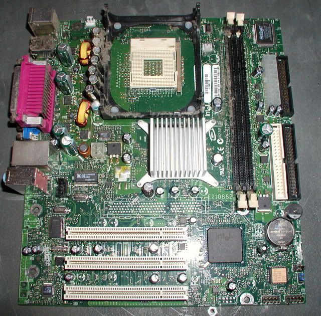
Old PC mobo you could care less about:(because you will be destroying it)
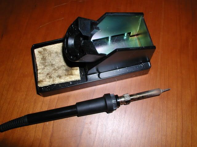
Soldering Iron: (In the pic, I use a soldering station, but for this project, just go grab a cheap $10 30w iron from home depot)
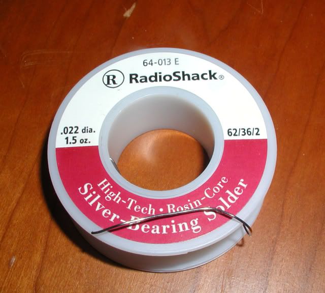
Solder: (I use rosin-core silver-bearing, doesn't have to be silver-bearing though; reg. rosin-core's cheaper)
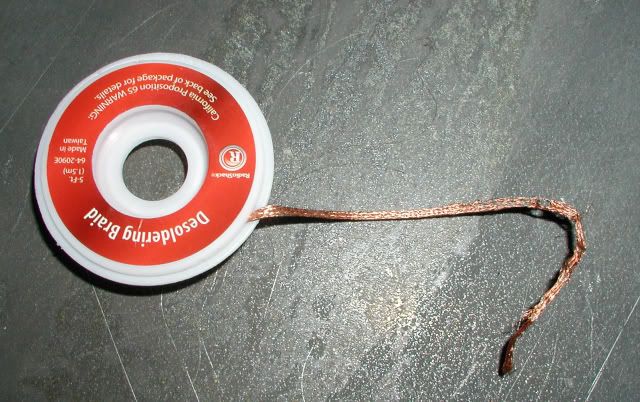
Soldering Braid: (optional I guess, if you just want to maul the crap out of the PC mobo w/your desoldering iron)
Flux:
Metal Plate:(For discharging the solder from your desoldering iron)
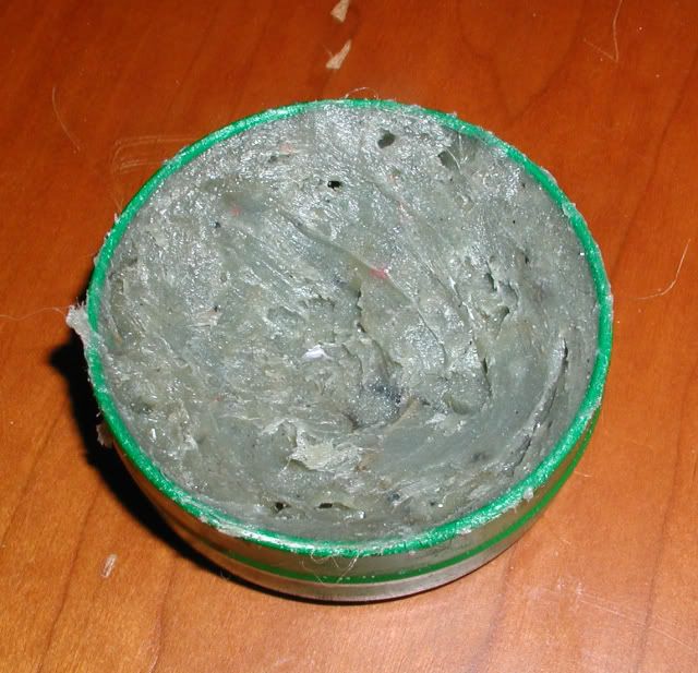
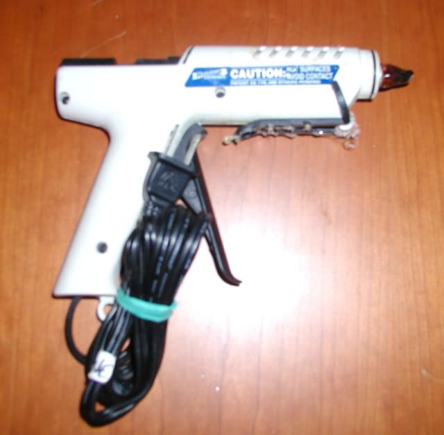
Hot Glue Gun:
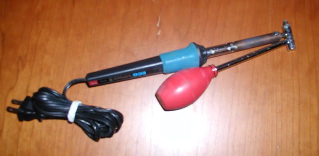
Desoldering Iron: (Radio shack has one - 45w I think. That'll work)
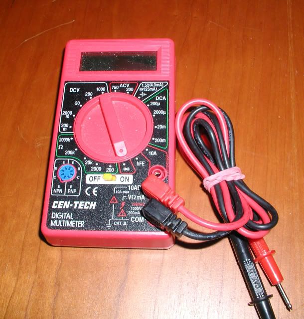
Multimeter:
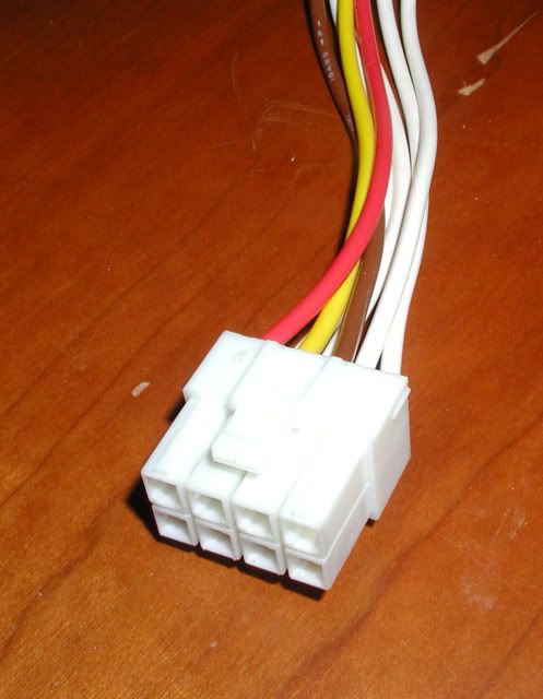
JST 8 Pin Naomi Mobo CN (Connector) Part No. VLP-08V: http://triplemoonstar.brinkster.net/seg ... efault.asp
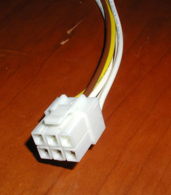
JST 6 Pin Naomi Mobo CN Part No. VLP-06V: http://triplemoonstar.brinkster.net/seg ... efault.asp
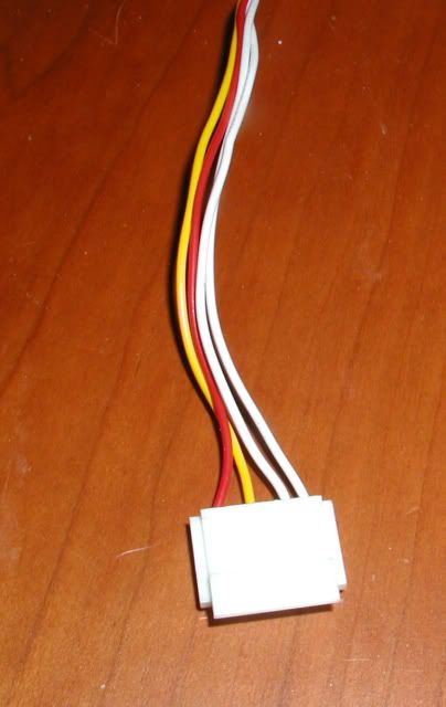
JST CN Part No. H6-SHF-AA: (Optional GD-Rom 6 Pin Power CN) http://triplemoonstar.brinkster.net/seg ... efault.asp
Optional Cosmetic Stuff:
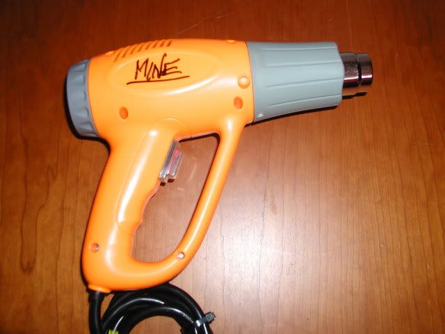
1. Shrink tubing & Heat gun (a hair dryer will work)
2. Zip-ties
Part 1: Removing the female ATX CN from the PC mobo:
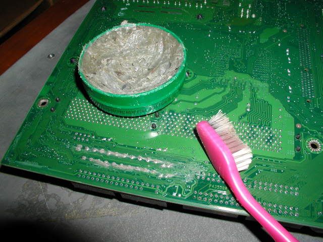
First, plug in your desoldering iron & let her heat up. Flip over your PC mobo and locate the underside pins of the female ATX CN. Now, spread some flux on the 20 pins, so that they're nice & coated.I used a toothbrush, but it doesn't matter what you use, just get flux on them, like in this pic here:
Next, working over the metal plate, take your fully preheated desoldering iron, and depress the bulb. At a bit of an angle, center the tip of the iron around a pin, and as soon as you see the solder loosen (1-2 seconds) let up on the bulb, and the iron will suck up the loosened solder.
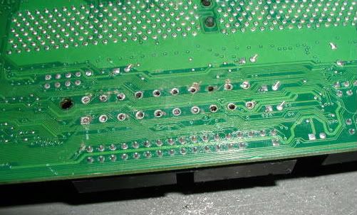
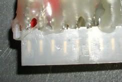
Before you repeat, aim the tip of the iron at the metal plate you're working on, and discharge the solder onto the plate. Then, repeat with all the other pins, until it pretty much looks like this:
From here, you've got 2 options:
1. Wipe the board down, reapply more flux, and continue to gouge the living daylights out of the mobo w/the desoldering iron, until you suck out all the solder.
2. Heat up your regular iron, wipe down the board, & reapply a bit more flux. Then, using the braid, (keep in mind the braid will get hot, so either work fast, or wear padded gloves) lay the braid on the pin, and place the heated soldering on the braid. This will suck up any excess solder.
Like I said, don't be afraid to burn the mobo to hell; and if you end up ripping a few pins out, don't stress too much. Check the diagram below, as they may not even have been pins that you'd need. Bottom line is, don't try and "pry" the CN out of the mobo, as that move will most likely end in sadness. Since the mobo is sacrificial anyhow, take a small file to the pins if you have to - Hell, this your chance to "productively destroy" something :]
Now, provided all went well, the female ATX header should come right off. Congrats, you're half done :] Don't forget to unplug your desoldering iron.
Part 2: Making the adapter:
It's all easy from here -
Please note, that for this tutorial, I slapped mine together in 10 mins, so you may want to use longer wires, or take a bit more care in certain areas, obviously.
Anyhow, the next part involves actual soldering, but for the sake of ease, I've made it as simple as possible.
Next thing you're going to do is "tin" your pins & wires. All this means, is that you're going to coat everything w/solder, so that when you put 2 things together &
touch them w/your iron, the solder will melt, and those 2 things will be connected.
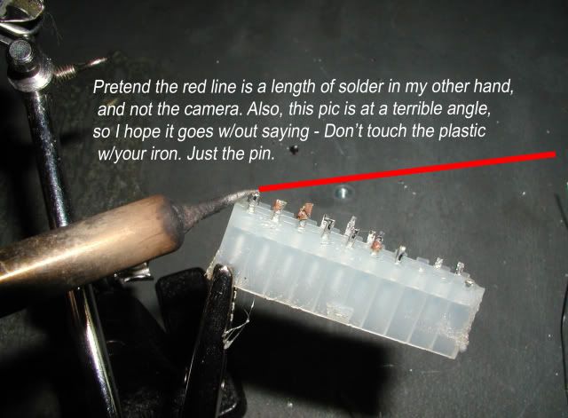
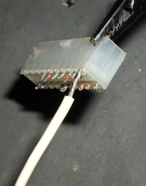
First, secure your female ATX CN, so that it is standing straight up, or, if you plan on soldering more in the future, pick up a third arm, as shown in the pic. To make things even easier, go ahead and wipe the pins with flux. With your iron in one hand, and a length of solder in the other, simultaneously touch the solder and the iron to each pin, coating it with solder.
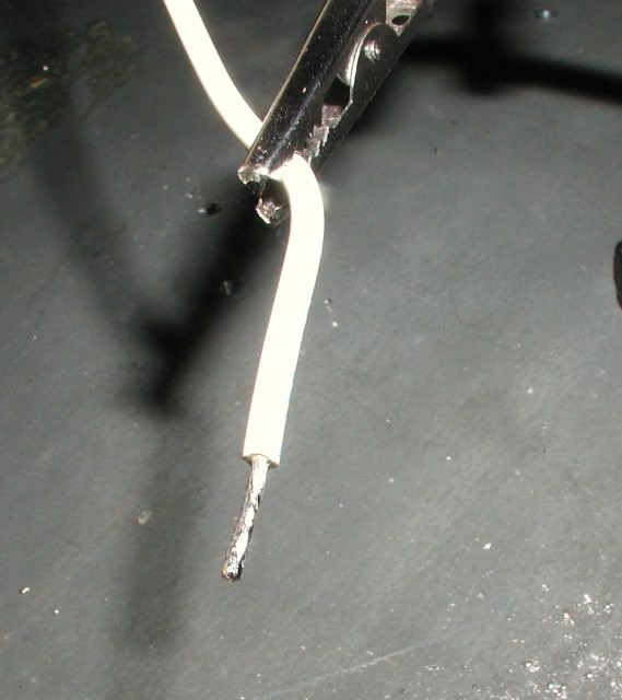
Next, strip the ends of the wires from the JST CNs, and tin those in the same manner.
:smt075Important: Skip this next step, and your adapter won't work, guaranteed.
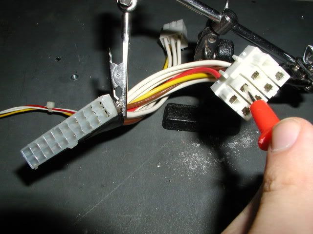
Now, before you start wiring the JST CNs to the ATX CN, you need to connect these 2 pins together, permanently. They do not go to anything else, nor do they touch anything else. Just each other:
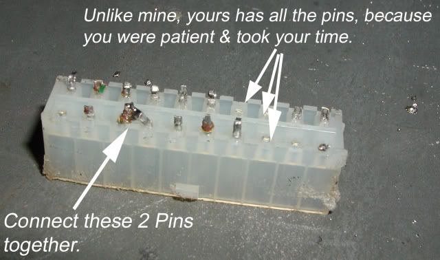
In the pic, I just bent them towards each other & covered them w/solder. However, if you're feeling up to it, you can just jumper them with a single wire. Either way, just make sure they're connected.
On a PC, those pins are sense & ground, which need to be shorted, in order for an ATX psu to turn on. On your PC mobo, the pcb shorts them automatically. What we're doing, is basically just shorting them manually. Also, keep in mind that when you jumper these 2 wires, it will put your PSU into an "always on" state.
So if your psu does not have it's own power switch, then the moment you plug it in w/the adapter attached, it will turn on. Alternatively, you could always run it through a power strip w/a switch to use instead.
Ok, last step:
Now that all your wires, and all the pins, are tinned, in order to connect a wire to a pin, all you need to do is touch a wire to a pin, touch the iron to both for a moment, release, and voila - you've officially soldered something.
Here are the diagrams for the CNs:
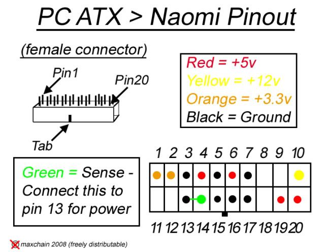
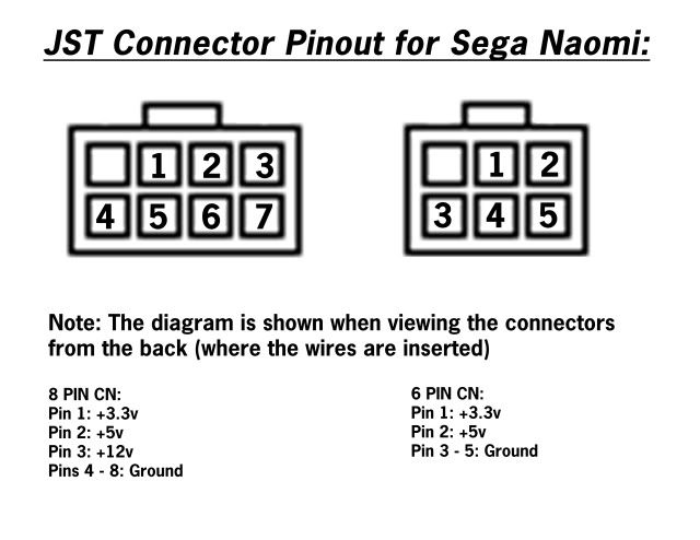
It is verrrrrrry important that you connect the pins to the proper wires. If, for any reason at all, the diagram below confuses you, please verify what you are about to do, w/pictures preferably, in a forum post, before you do it. Otherwise, the results are on you pal, and not from this faq.
Lastly, you will need to insulate the pins. Just take your hot glue gun, and glob hot glue all over the pins, whilst ensuring that the glue dries w/none of the pins touching. (less of course the ground & sense pins we purposefully jumpered, as described above) Once finished it should look like this:
And you're ALMOST done.
Just in case you did happen to get overly creative with your wiring - fortunately for you, the multi-meter exists.
Take your meter and set it to "continuity". On most meters, the symbol on the dial looks like an arrow with a line through the tip. Assuming your meter is digital, touch the 2 leads together. If it the readout says 1.0 when they are not touching, and 0.0 when they are, you're on the correct setting.
Now, you are going to doublecheck your work w/the diagram above. Do not plug anything in. You cannot shock yourself while doing this.
Take one of the leads from your meter (doesn't matter which one, red or black), and insert it in one of the pins on one of the JST CNs. For example:
According to the diagram above, this pin needs to be getting +5v. Ok, so keeping that lead inserted, take the other lead, and touch it to the ATX CN pin where +5v should be. If you wired this pin correctly, your meter readoout should change from 1.0 to 0.0. If not, use the meter to find out where it is wired, and rewire it accordingly. Also, just to be safe, even if that +5v is wired correctly, make sure that it is only wired to +5v, and not to any other pins as well (less other +5v pins)
Repeat this process for all the other pins. I cannot stress enough the importance of checking your work w/a meter. Testing your adapter by plugging it into your Naomi is not a good idea dude.
Finally, I would at least wrap the hot glued portion w/electrical tape for insulation. Or, you can look at the extras option below.
Congratulations. You are now an engineer. (not like like the ones who drive trains)
Somewhat Optional (but recommended) Extras:
Ugly, no? For a decent look, get some shrink tubing, and wrap it around the hot glued portion, shrinking it w/the heat gun.
Also, you can use zip-ties to manage the loose wires.
And yes, use longer wires than the one shown in the picture.
:smt075The "I don't care how easy it is, I don't want to solder, period." Method:
Fine. Parts needed:
Naomi JST Connectors: (6-Pin, 8-Pin, & optional 6-Pin GD-Rom cable) http://triplemoonstar.brinkster.net/seg ... efault.asp
ATX 20 pin Power Supply
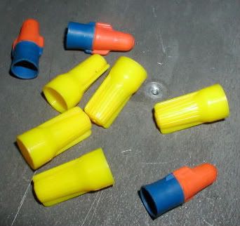
Twist-on Wire Connectors:
Wire Stripper
Multimeter (in case you just skipped to the bottom for the solderless option, checking your work with a meter is still a necessity! Read through the last part of the solder-type option above BEFORE testing your psu out on your Naomi!)
First, from the 20-pin connector on the psu, cut the green wire, one of the black wires, & strip the ends. Twist the wires together, and screw on a Twist Cap.
Next, cut these wires, directly from the psu 20-pin CN, and strip them: (universally color coded on all PC ATX psus, but check the diagram above, just in case)
Red = +5v
Yellow = +12v
Orange = +3.3v
Black = Ground
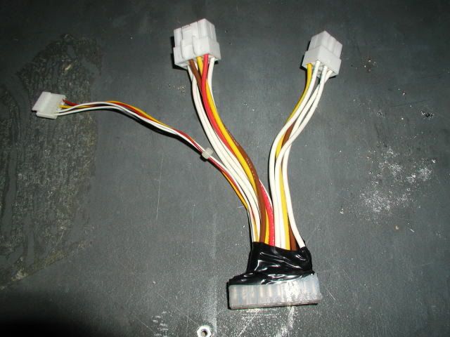
Following the diagram below, twist the wires from the psu together w/the corresponding wires from the JST CNs, and then secure them with twist-caps. Because there are more +12v wires from the JST CNs, that there are from the psu, it's ok to twist all 3 together.
Not much of an adapter at all really, but a power supply that'll do the job.
Best of luck everyone -